This is an object that represents a Pan, tilt, zoom camera and allows SP to control it.
For details about how to setup such a workflow, please refer to this page.
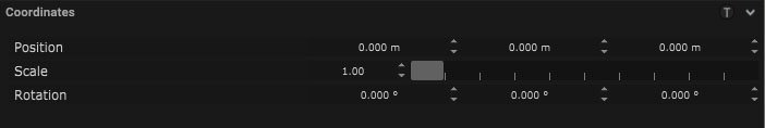
Coordinates
| Name |
Description |
| Position |
This will move the object along X, Y and Z axis in the local space. |
| Scale |
Scale of the coordinate system. To scale the Object check the settings under “Display” |
| Rotation |
Rotation of the object along X, Y and Z axis. |
![]()
Camera Parameter
| Name |
Description |
| Projection |
- Perspective – This camera view allows for a three-dimensional view, representing depth, width and height.
- Orthogonal – This camera view gives a two-dimensional view of the three-dimensional space.
|
| Field of View |
The field of view is part of the area of the world that is visible through the camera. |
| Aperture |
The aperture of the camera can be set here. |
| Focus Distance |
This is the minimum distance where the camera is still able to focus. |
| Focus Length |
This is the maximum distance where the camera is still able to focus. |
Lens Distortion
| Name |
Description |
| K1 |
This is a lens distortion parameter. |
| K2 |
This is a lens distortion parameter. |
| K3 |
This is a lens distortion parameter. |
| P1 |
This is a lens distortion parameter. |
| P2 |
This is a lens distortion parameter. |
| Center X |
Movement of the center point along the X axis. |
| Center Y |
Movement of the center point along the Y axis. |
| Overscan |
extends the render region beyond the main image coordinates |
| Squeeze Factor |
ratio of horizontal to vertical information captured by an anamorphic lens |
Panel
| Name |
Description |
| Resolution |
The resolution of the camera can be set here. |
| Panel Size |
The panel size can be adjusted by width and height. |
| Aspect Ratio |
The aspect ratio of the output can be set here. |
| Lens offset |
The offset between the lens from the camera sensor |
Frustum
| Name |
Description |
| Frustum Source |
The source to define the length of the frustum. |
| Frustum Length |
If the frustum source is set to custom length, this defines the length of the frustum |
| Display Type |
How the body of the camera is drawn on the viewport |
| Display Frustum |
When on, a frustum would be displayed for the camera |
| Display Targetline |
When on, a line would be drawn between the camera and where it is looking at |
| Near Clipping |
This is a set distance from the camera where any objects closer to the camera than this won’t be rendered. |
| Far Clipping |
This is a set distance from the camera where any objects past this distance won’t be rendered by the camera. |
| Focus Range |
What is the range of focus on the camera in meters |
Mapping
Input Mapping
Filters
Output Mapping
Target
| Name |
Description |
| Target Object |
An object can be selected for the camera to follow. |
Automatic Pan/Tilt
| Name |
Description |
| Safe Range |
The amount of safe range on the Pan and Tilt axis |
| Smoothing |
The amount of smoothing for the output Pan and Tilt values |
| Use Distance |
|
Automatic FOV
| Name |
Description |
| Border |
The amount of border around the frame of the camera to leave as extra space |
| Smoothing |
The amount of smoothing for the output zoom value |
| Use Object Points |
Should be ON, if the vertices of the object are used to frame the camera |
Automatic Focus
| Name |
Description |
| Smoothing |
The amount of smoothing for the output focus value |
| Focus Target |
- Center Point – the center of all targets
- Nearest Point – the nearest target
- Farthest Point – the farthest target
|
Settings
| Name |
Description |
| Min Pan |
This is the minimum distance the camera can move along the X axis. |
| Max Pan |
This is the maximum distance the camera can move along the X axis. |
| Min Tilt |
This is the minimum distance the camera can move along the Y axis. |
| Max Tilt |
This is the maximum distance the camera can move along the Y axis. |
| Tilt Offset |
This offsets the tilt distance by the number of degrees set. |
| Field of View H |
The FoV curve |
| Focus Distance |
The focus curve |
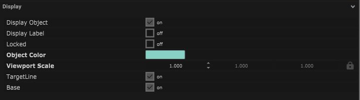
Display
| Name |
Description |
| Display Object |
If ticked, the object will be visible in the scene. If un-ticked, the object will not be visible. |
| Display Label |
When on, there will be a label displayed next to the object. |
| Locked |
When un-ticked, it activates keyboard shortcuts – pressing ‘E’ allows you to move and ‘R’ rotate. |
| Object Colour |
Double click the colour block and this will open a colour picker. This can be used to change the object display colour. |
| Viewport Scale |
Dimensions of the object in the viewport in meters. |
| Target Line |
When ticked there will be a line from the center will appear this shows the direction the camera is pointing. |
| Base |
When on the base of the PTZ camera will be visible. |
![]()
Display Settings Tutorial
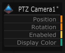
Node Based
The object can be controlled and used as a node. The node is created by clicking and dragging the parameter on to the board.
![]()
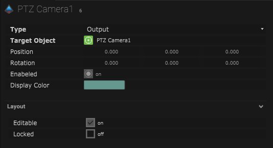
| Name |
Description |
| Type |
- Input – The nodes input values are determined by incoming values from an external source.
- Output – The node is outputting data to another source.
|
| Target Object |
This is the object that will either be affected by the incoming values or output information. |
| Position |
The directional XYZ values will be displayed here. |
| Rotation |
The rotational XYZ values will be displayed here. |
| Enabled |
When on, the parameter is active and enabled. |
| Display Colour |
This colour block can be changed by changing the parameter. |
![]()
Layout
| Enabled |
When on, the parameter is active and enabled. |
| Locked |
When on, the node is locked into its position on the board. |