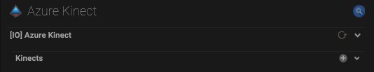
To use the Azure Kinect IO connection, the kinect sensor(s) must first be added using the + button.
Kinect Setup
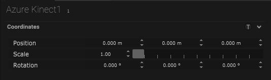
Coordinates
| Name | Description |
|---|---|
| Position | The position of the kinect along the XYZ axis can be set. |
| Scale | The scale in meters can be set here. |
| Rotation | The rotation on the XYZ axis can be set. |
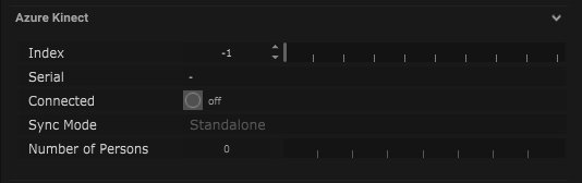
Azure Kinect
| Name | Description |
|---|---|
| Index | The index number of the incoming kinect can be set. |
| Serial | The serial of the incoming kinect will be displayed when connected. |
| Connected | When on, the kinect is connected. |
| Sync Mode | |
| Number of Persons | The number of people the kinect is required to detect can be set here. |
Settings
Any active Azure Kinect already connected to the computer can be added to the scene by clicking the magnifying glass. This will open display the serial number of all active Azure Kinects and the correct one can be selected.
| Name | Description |
|---|---|
| Open Viewer | Pressing this button opens a viewer that displays the kinect feed. |
| Viewer Image |
|
| Depth Mode |
|
| Colour Format |
|
| Resolution |
|
| FrameRate |
|
| Power Frequency |
|
| Sensor Orentation |
|
| GPU Device ID | The ID number of the GPU can be added here. |
| Tracker Processing Mode |
|
| Update Colour | When on, the changes in colour will automatically be updated. |
| Update IR | When on, the changed in IR will automatically be updated. |
| Update World | When on, the world will automatically be updated. |
| Update Vbo | When on, the vertex buffer object will be automatically updated. |
| Update Body | When on, the skeleton body will automatically be updated. |
| Display Device | When on the device will be displayed. |

Vbo Options
| Name | Description |
|---|---|
| Display Vbo | When on, the vertex buffer object will be displayed. |
| Draw Point Size | |
| Display Mesh | When on, the mesh will be displayed. |
| Capture | Pressing this button will add the Vbo to the objects panel and open its own parameter window. |
| Near Clipping | The near clipping range can be set here. This is the closest rendering distance. |
| Far Clipping | The far clipping range can be set here. This is the furthest rendering distance. |
| Clip Floor | When on, the floor will be rendered in the clipping distance. |
| Floor Height | The height of the floor can be set here in meters. |
| Clip With Object | When on, a set object can be added into the clipping frame. |
| Primitive Cube | The clipping object can be selected here. |

Calibration
| Name | Description |
|---|---|
| Align Tool | Pressing this button will open the world calibration window. |
Calibration – World
- The SP (Stage Precision) world reference point needs to be set. This can be done by clicking in the black box, this will open a drop-down list and the reference point can be selected.
- The source reference point needs to be set. This can also be done by clicking in the black box, opening a drop-down list and the reference point can be selected.
- The calibration mode can be set to manually take frames or automatically take frames.
- Next the Calculation Mode must be set from the options: CRSPD_PTS_TF, Plc or Axis.
- The calibration can begin by pressing the button ‘Take Frames’ or ‘Click to Start’.

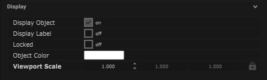
Display
| Name | Description |
|---|---|
| Display Object | If ticked, the object will be visible in the scene. If un-ticked, the object will not be visible. |
| Display Label | When on, there will be a label displayed next to the object. |
| Locked | When un-ticked, it activates keyboard shortcuts – pressing ‘E’ allows you to move and ‘R’ rotate. |
| Object Colour | Double click the colour block and this will open a colour picker. This can be used to change the object display colour. |
| Viewport Scale | Dimensions of the object in the viewport in meters. |