
There are different ways to get tracking information within SP. One of them is to extract infromation from a set of point cloud data and do blob tracking from that.
There are in general 2 main groups of point cloud that SP can process to do blob tracking on. They are 2D point cloud (like from 2D LIDAR systems) or 3D point cloud.
Currently the list of point clouds supported within SP are:
Initial Setup for Point Data Provider
To get started, you would first need to get the sensor connected and configured with SP to generate point data. The overall idea is to ensure that there is a connection between the sensor, and configure the sensor to the range, sensitivity, resolution, etc so that it fits your application. For details on exactly how to setup and configure the various sensors, please refer to their respective document.
2D Point Cloud
3D Point Cloud
Calibrating / Aligning the Sensor in 3D Space
In the previous step, we have added the sensor and are receiving data from the sensor. Now is a good idea to align the sensor so that its orientation and position matches to what we expect.
To do so, we recommend that follow the steps below:
- you define an origin for the physical space that you are working in, and define the direction of your X, Y, and Z axis.
- Look at the surrounding for interested vertex / location that can be picked up by the sensor, measure and record the X,Y,Z values relative to your defined Origin point. At a minimum, there should be at least 3, ideally with different values for all X, Y and Z axis.
- Under the sensor that you are working on, within the Tools section, create a Point Align Tool.
- Add the same number of Points to this tool as the points that you have measured.
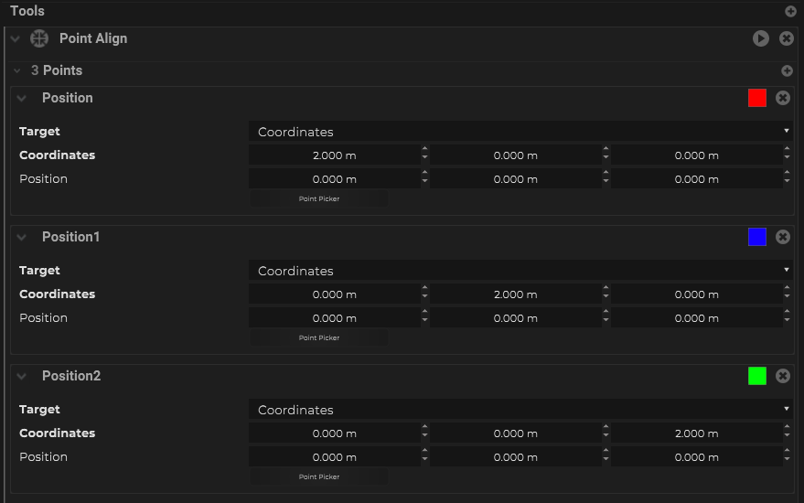
- Change the “Target” mode to be “Coordinates”, and enter the measured X,Y,Z values to the “Coordinates” field
![]()
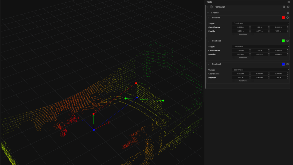
- For each of the points, below the “Position” field, there is a button for “Point Picker”, click on this button
- Go to the viewport within SP, navigate to the area where you can see the sensor’s data that matches the location that you have chosen. Click on that point from the sensor data.
- Repeat this Point Picker steps for the remaining other points in your tool.
![]()
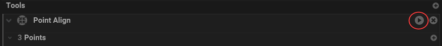
- Once all of the points in the tool have been picked, click on the “Play” icon at the top right of the tool to run the calibration.
![]()
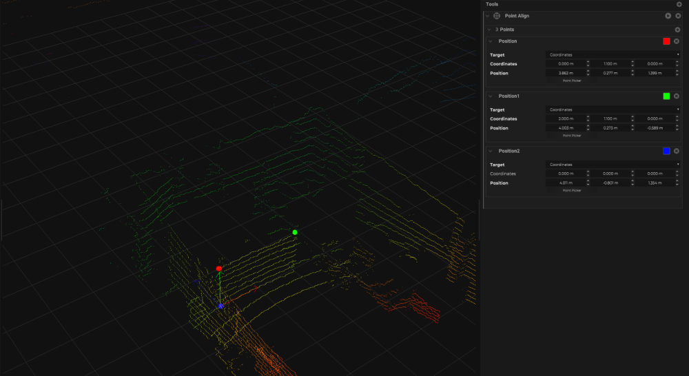
- This should orient the sensor within SP to match how it is mounted in the physical space
![]()
Fine Tuning the Tracking
By now, the sensor is sending data into SP, and is being processed by SP, and some of the objects are begin tracked and ID by SP. This is a good time to start looking into the settings and fine tune the blob tracking algorithm.
Fine Tuning the Data from the Sensor
For a 2D system, some of the settings that you should look at would be under the sensor object – Cluster:
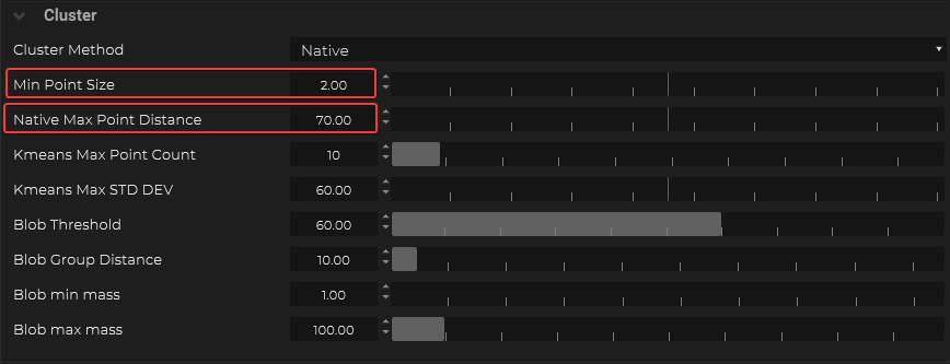
- Min Point Size – the minimum size the a blob can be to be considered as a valid point
- Max Point Distance – the distance between 2 valid point
For a 3D system, some of the settings that you should look at would be defined under the VBO Clustering Filter within the sensor object – Maps – VBO Clustering:
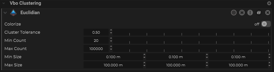
- Cluster Tolerance – defines the tolerance / senstivity of the blob
On top of this, there are additional filters for 3D system that is provided by SP to help isolate and clean up the data from the sensor. These are all access from the sensor object – Maps – VBO Filter. For example, there are options for:
- background subtraction
- defining a clipping object
- defining outliers
What’s next
The next step is to pass this point data into a Volume object for further processing. Please refer to this page for more information.