
Any sensor which provides an Image Provider can be used for Blob Tracking.
This could be infrared cameras, depth cameras, head map cameras as well as RGB cameras.
| Device | RGB | Depth | IR Filter | Notes |
|---|---|---|---|---|
| Azure Kinect | |
|
|
|
| CommonVisionCamera | |
|
|
different filter are available |
| Galaxy Camera | |
|
|
different filter are available |
| Image Sensor | |
|
|
depends on the connected camera |
| Optitracks | |
|
|
|
| Real Sense D435 | |
|
|
Initial Setup for Image Provider
To get started, you would first need to get the sensor connected and configured with SP. The overall idea is to ensure that there is a connection between the sensor, and configure the sensor that fits your application. For details on exactly how to setup and configure the various sensors, please refer to their respective document.
Doing Blob Detection from the provided Image
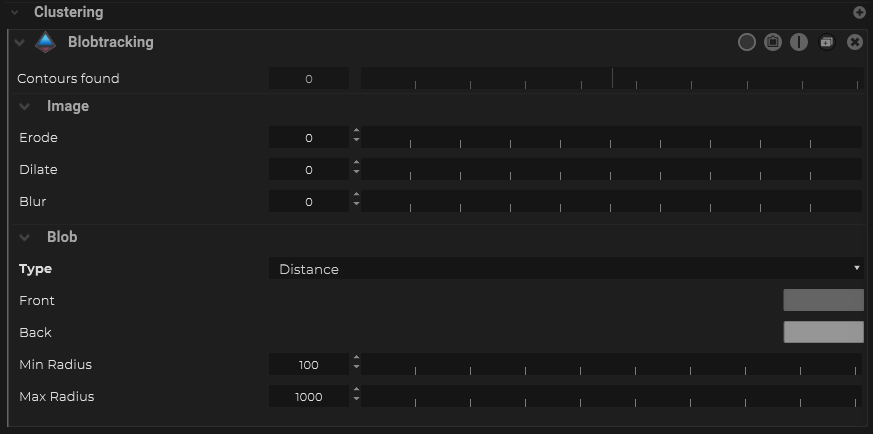
- Within the sensor object, under the Maps section, add a Blobtrtacking Clustering filter.
![]()
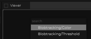
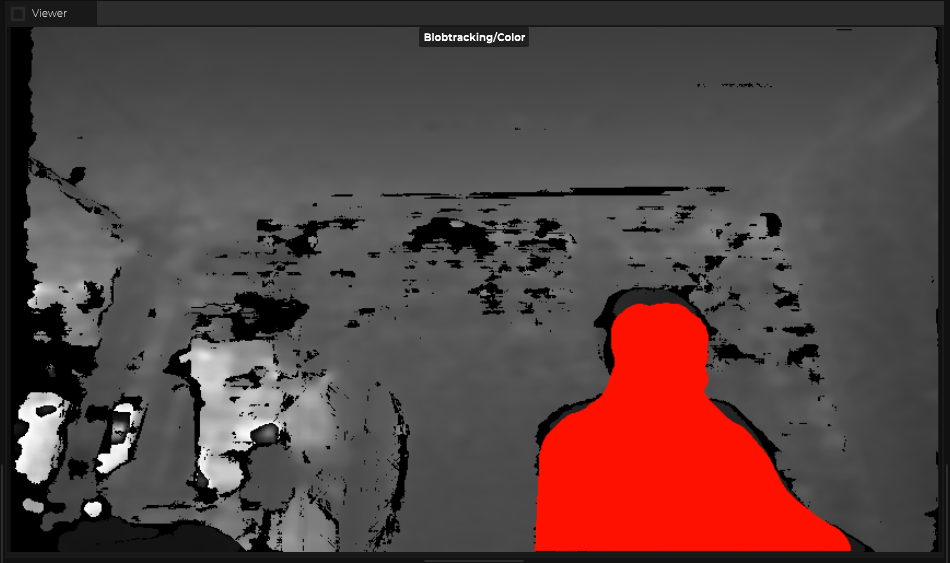
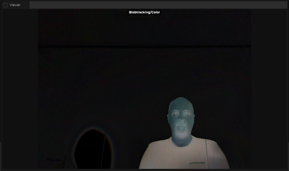
- Before continuing, it is a good idea to open up a Viewer window to preview how the blob detection algorithm is working. Right click on the Viewer window, and select “Blob Detection/Color”.
![]()
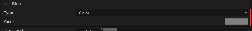
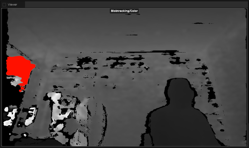
- If the sensor is a standard RGB or BW image, select the color value that should be used as an identifier for an object of interest. Adjust the Threshold so that the cut out works best for your application
![]()
![]()
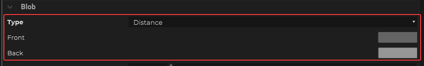
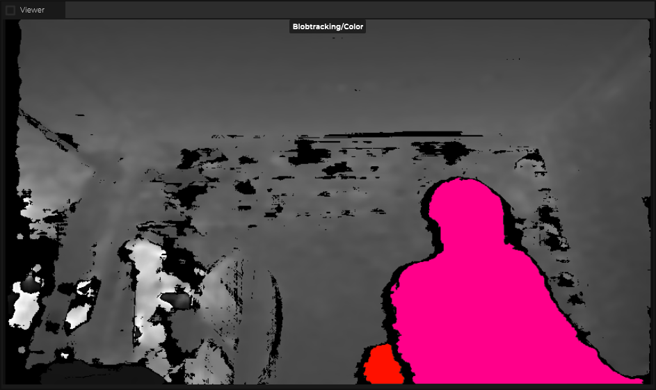
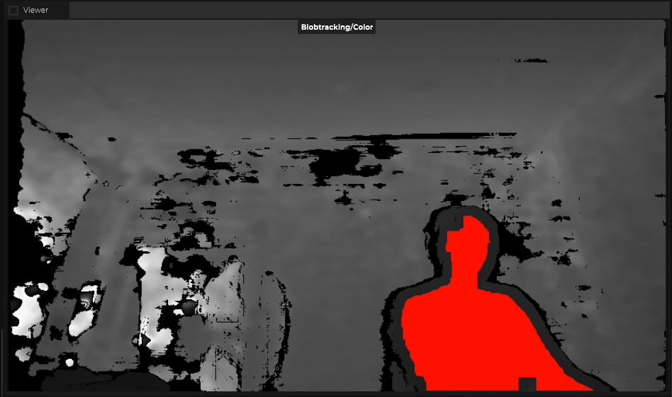
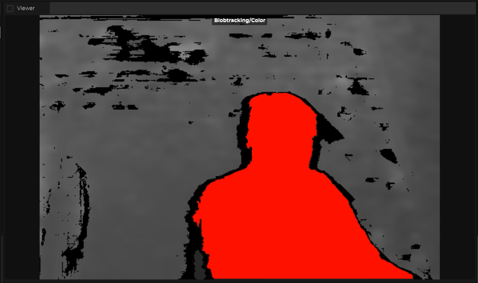
- If the sensor is a depth camera, chose the type to be Distance and adjust the greyscale value for the front and back plane to define your detection zone.
![]()
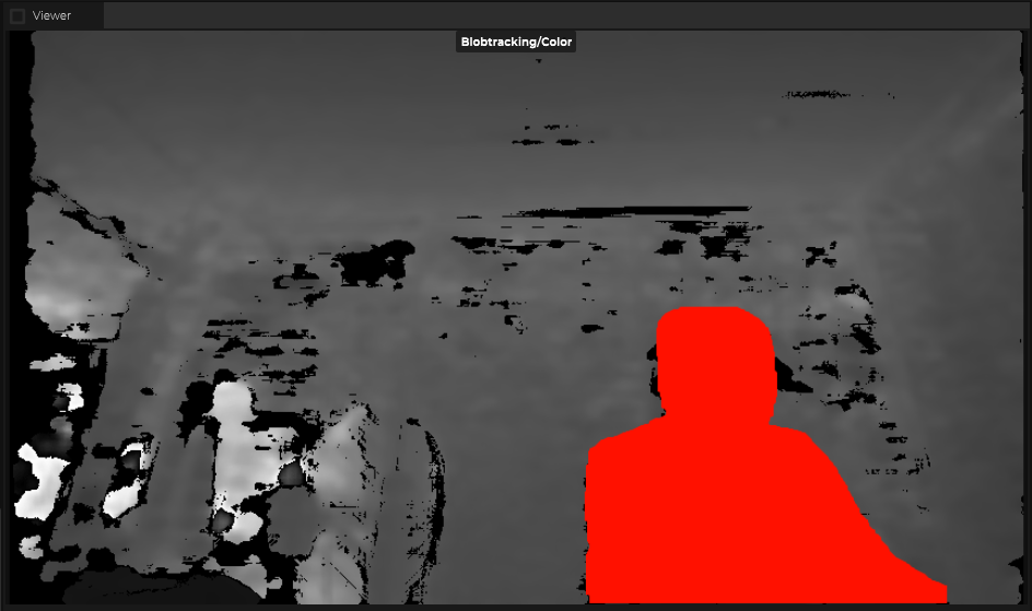
- Fine tune the Min Radius and Max Radius to help ignore false positive for the blob detection
![]()
- There is also the option to Erode,
![]()
- To Dilate
![]()
- To Blur your source image from the sensor
![]()
Fine Tuning the Blob Detection Algorithm
SP provides additional filters for you to clean up the base image to better extract the objects out of an image. Below is a list of them:
| Name | Settings | Viewer |
|---|---|---|
| Crop |  |
 |
| Polygon | 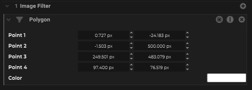 |
 |
| Mirror |  |
|
| Difference | 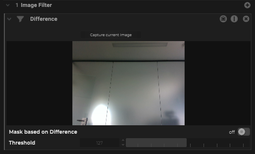 |
 |
| Background Subtraction |  |
 |
Getting Tracking Data from the Blob Detection
An Image based blob detection would only be able to get the location of the blobs in a 2D space relative to the image sensor. SP has the ability to project and extrapolate 3D data from the sensor.
For example, is the sensor is mounted at the ceiling and it is pointing down towards the floor.
Calibrating / Aligning the Sensor in 3D Space
The first thing that needs to happen is to find out the exact orientation of the image sensor.
To do so, we recommend that follow the steps below:
- Prepare a screen that can disable some markers. This can be a monitor, a TV, a LED wall, etc. We will use this screen to as a reference to determine the location of the image sensor. So please make sure the screen is located in an area where the sensor can see it.
- Measure the exact dimension of the screen (no including the bezel, only the area of the display).
- Determine an Origin point within your physical space, and meaure the distance between the your screen and your origin to determine the coordinate of X,Y and Z axis relative to your origin point.
- Create a Calibration – Single Screen and enter the properties like the Screen Dimension and the Screen Resolution along with the coordinate of this screen.
- Within the Calibration Screen, under “Screen”, generate the markers for the screen. Please try to generate at least 4 markers for the screen.
- Export this marker pattern and load this pattern onto you calibration screen.
- Under your image sensor object, within the Tools section, create a tool for “Screen Calibration with Marker”
- Open up the Calibration wizard, and select your image provider, and your calibration screen
- Add one Observation to capture a still image for calculation
- Press the “Play” button to run the calibration. Based on the provided information, SP will calculate the location of the image sensor relative to the screen.
Projecting the Sensor Data to a Plane
Now that we know the orientation of the sensor, we can combine that with the actual image from the sensor and project that onto the floor and get the actual location of where objects are.
- Create a Plane object that matches the floor or the flat surface that your sensor is pointing at by changing the coordinate, rotation and plane size of the object.
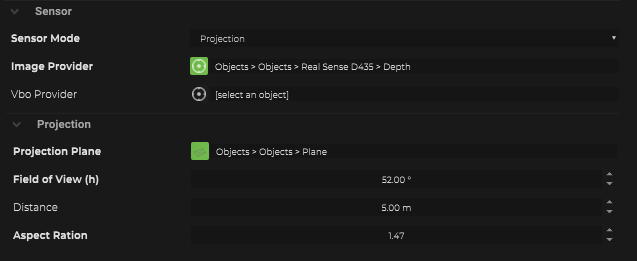
- Within the image sensor object, under Image Sensor – Sensor – Sensor Mode, Choose “Projection”.
- Adjust the Field of View, and Aspect Ratio so that it matches your image sensor
- Choose the Image Provider to be itself.
- Choose the Projection Plane to be the Plane object that was created above.
Once all of this has been configured, you can see that the 2D blob from the image sensor has now been projected onto the plane and a tracked object has been created by SP to represent it in 3D space.
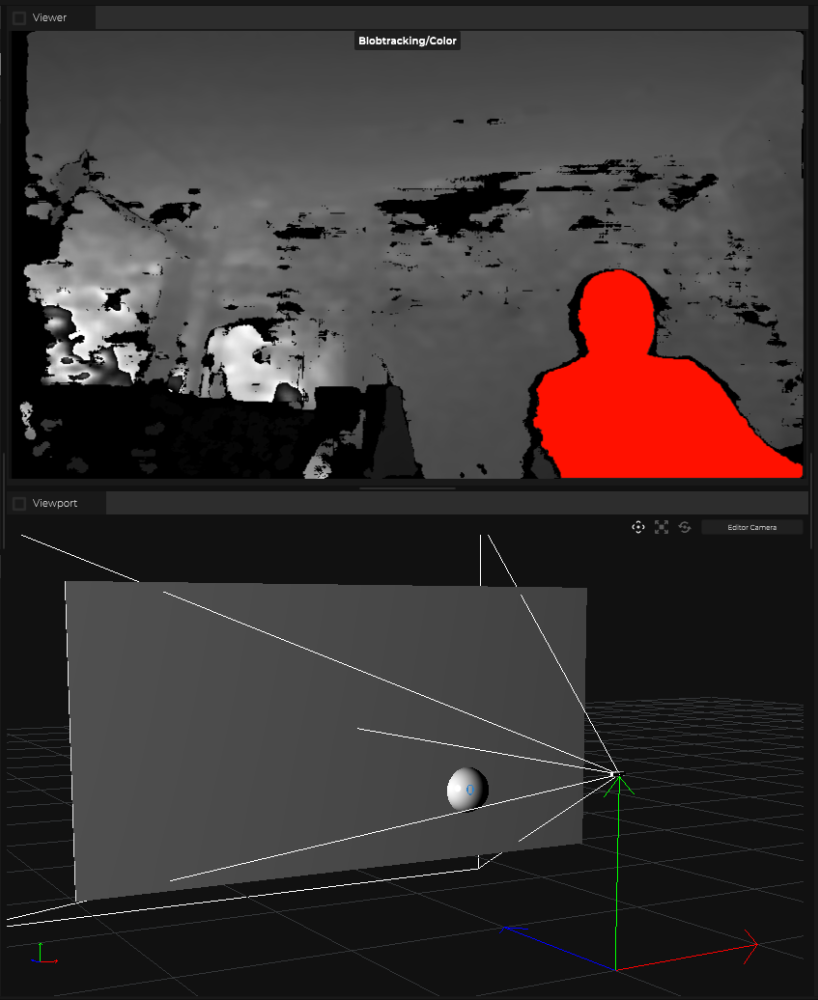
Note: this screenshot is taken after a volume object has been created. Please follow the next step to create a volume object and how to use the volume object to get IDs of tracked blobs.
What’s next
The next step is to pass this point data into a Volume object for further processing. Please refer to this page for more information.