
The main objective of the Alignment with Marker Tool is to align the tracking system using predefined markers in 3D space instead of patterns on a screen.
Prerequisites
- Media Input into SP
- A camera object within SP
- A Lens Profile for the camera
- A supported tracking system
- A map input within the camera object to allow the tracking system to be driving the camera in SP.
In order for this tool to work properly, the camera need to have a properly calibrated lens. At the end of this process, the tracking system would be aligned and the camera would be placed correctly at the relative position to the markers used for the calibration.
The process of this tool is to place markers in the 3D space and have accurate measurements of their exact coordinates and using these markers as reference to align the tracking system.
Adding Markers
- Add a Measurement Point from the object tree, and place this point at the coordinate that matches the coordinate of a physical marker in the physical world.
- Repeat this process for all of your measurement points.
Adding the Alignment with Marker Tool
Once everything has been setup and the camera object is linked properly to the incoming data, the Lens Calibration process can begin.
Go to the camera object, and under the Tools tab, add a new tool under the Calibration folder. Depending on the different situation, a different tool can be used. For more information, click here.
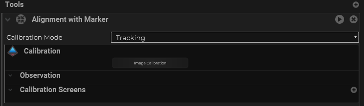
There are different Calibration modes available depending on the situation with the tracking system and the setup.
| Name | Description |
|---|---|
| Tracking | This mode is mainly used for a camera that can be tracked as it moves to different locations in the venue |
| Nodal Origin | This mode is only used when lens needs to be swapped from the camera body and the nodal origin has been shifted slightly |
| Rotation Only | This mode is mainly used for a camera that is on a tripod / pedestal and would only be rotating on top of a fixed location |
| Pan Tilt Head | This mode is mainly used for Pan Tilt Head like PTZ cameras only. |
Once the correct mode is chosen for the setup that you have, can click on the “Image Calibration” button to open up the Image Calibration Wizard, and select the video signal source of the camera from the Image Provider.
Start Capturing
- move/rotate the camera (depending on the mode was chosen) and aim the camera such that it can see at least 4 of the markers in the space.
- press the “Capture” button to capture the frame for observation
- repeat this process for 5-6 times to get enough observations for calculation. It is a good idea to try to get the maximum range of motion possible when doing these captures.
Labeling the Markers from the Captured Observations.
- Once sufficient images have been captured for observations, you can click on the “Observations” button to open up the side panel to show all the captured observations.
- Double click on one of the observations to view the captured image.
- Press “F” on the keyboard will rescale the image to be full screen within the wizard UI
- Right click on the image where the measurement point is located to add a marker; a pop up list would show all the measurement points in the SP project, select from that list the measurement point that matches the location of the selected marker. Repeat this step for all of the markers visible in this image
- Press “ALT+(1-9)” to zoom in and cycle thru each of the markers added in the previous step.
- using the keyboard arrow keys to move the marker around to get to the exact pixel within the image of where the marker is located. You can hold down “SHIFT” while using the arrow keys for fine adjustments.
- Pressing “F” can go back to full screen view of the image.
- After finishing adjusting all markers location, press the “close viewer” button at the top right to close this observation, and go back to the previous view.