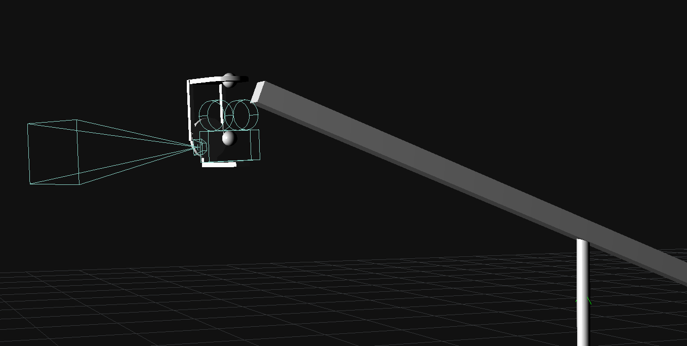
This is an example using the F4 (Mo-Sys) axis map inputs for a jib/crane that where there is
- a rotational pivot at the base
- a rotation encoder on the arm
- a remote pivot head mounted at the end of the arm.
- A camera is then mounted at the remote pivot head with a StarTracker mounted on the camera.

Adding all axis manually with offsets.
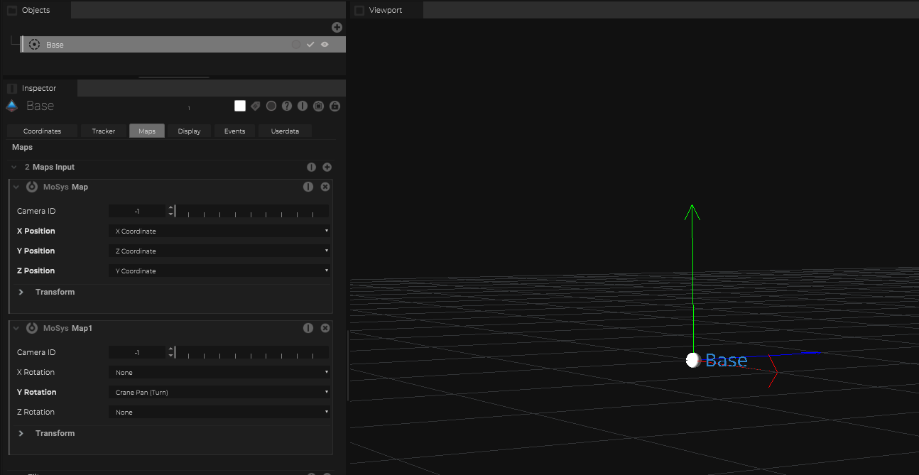
Adding an object for the “Jib Base”
In this case a Mo-Sys StarTracker is mounted on the Jib Arm to detect the room location as well as the pan of the jib.
To receive this location and rotation values, just add Tracker within SP and add the maps for position and rotation and define the axis.
In this example we are using all position axis as well as the jib pan axis
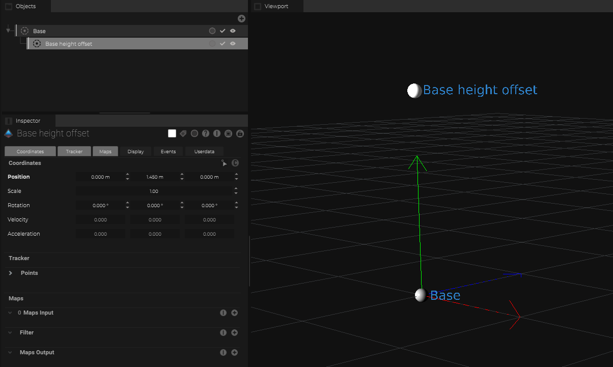
Base/Arm height offset (Arm tilt rotation pivot)
If needed, an additional object can be used to add an offset for the height within the object tree.
Just place it underneath the “Base Object” and define within the coordinates the needed offset.
This object should not have any map inputs.
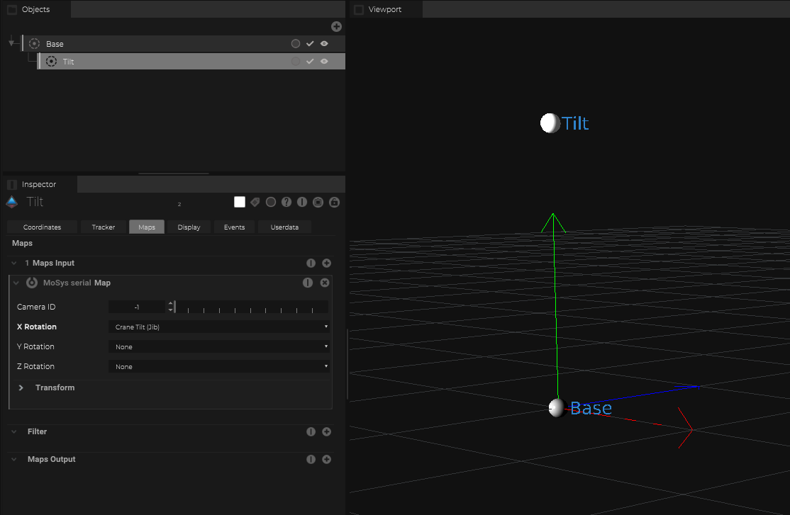
Jib Tilt rotation
So an additional object is already added and we can just use the same object and link the “Jib Tilt” to the object rotation X-Axis by adding a rotation axis map input.
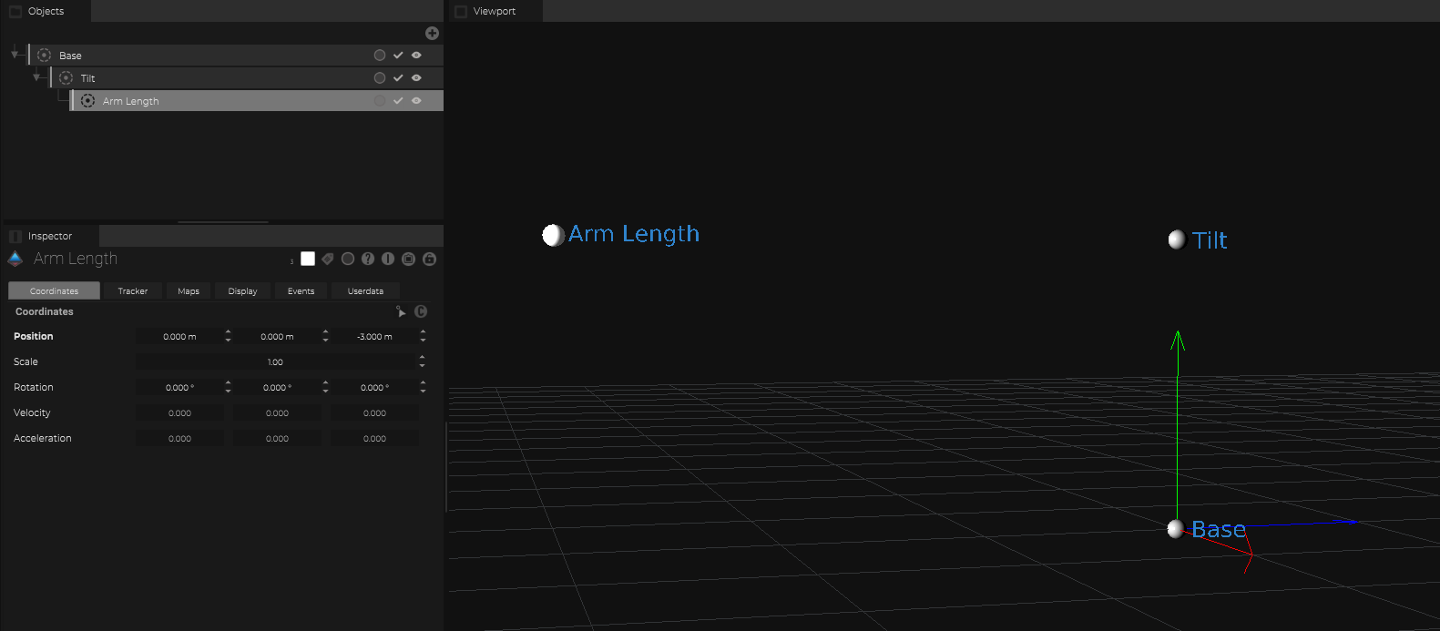
Jib Arm Length (Remote head pan pivot)
Add an object underneath the “Tilt object” and define the arm length.
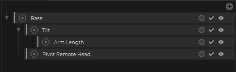
Jib “Neck” behaviour (Remote head tilt pivot)
Jib´s have the behaviour, that the “Neck” of the jib keeps the camera/remote head “level” (ie no roll).
This means we need for the pivot of the attached remote head at the location of the object “Arm Length” but not the rotation of it…
The rotation should just follow the base of the jib which includes the pan.
For this we need again an additional object but this object needs to be an parent of the “base”.
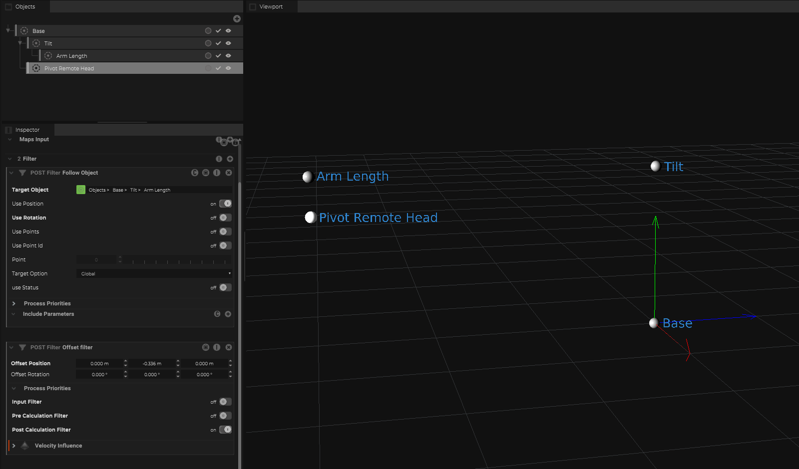
Now we need to link just the position of the “Arm Length”.
For this we can add a “Follow Object” filter and link as target the “Arm Length Object”.

To add an additional offset to this object, just add an offset filter.

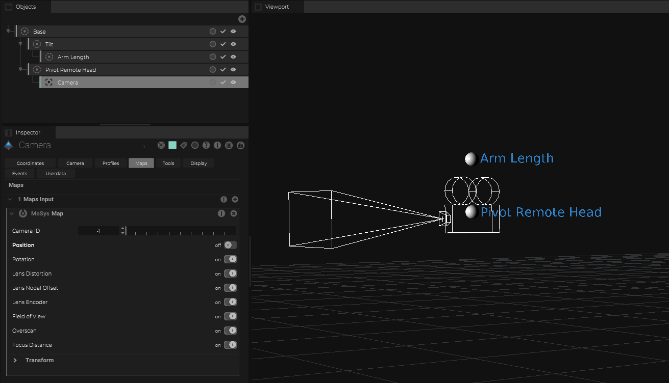
Camera (Sensor pivot)
Place now a camera object underneath the “Pivot Remote Head” and offset to the camera sensor.
The Camera object gets now the StarTracker map input.
Add objects/meshes to visualize the virtual jib