
This places a standard camera in the 3D space. This camera can be set to a perspective or orthogonal view.
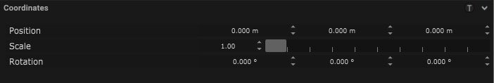
Coordinates
| Name | Description |
|---|---|
| Position | This will move the object along X, Y and Z axis in the local space. |
| Scale | Scale of the coordinate system. To scale the Object check the settings under “Display” |
| Rotation | Rotation of the object along X, Y and Z axis. |
Camera Parameter
| Name | Description |
|---|---|
| Projection |
|
| Field of View | The field of view is part of the area of the world that is visible through the camera. |
| Aperture | The aperture of the camera can be set here. |
| Focus Distance | This is the minimum distance where the camera is still able to focus. |
| Focus Length | This is the maximum distance where the camera is still able to focus. |
Lens Distortion
| Name | Description |
|---|---|
| K1 | This is a lens distortion parameter. |
| K2 | This is a lens distortion parameter. |
| K3 | This is a lens distortion parameter. |
| P1 | This is a lens distortion parameter. |
| P2 | This is a lens distortion parameter. |
| Center X | Movement of the center point along the X axis. |
| Center Y | Movement of the center point along the Y axis. |
| Overscan | extends the render region beyond the main image coordinates |
| Squeeze Factor | ratio of horizontal to vertical information captured by an anamorphic lens |
Panel
| Name | Description |
|---|---|
| Resolution | The resolution of the camera can be set here. |
| Panel Size | The panel size can be adjusted by width and height. |
| Aspect Ratio | The aspect ratio of the output can be set here. |
| Lens offset | The offset between the lens from the camera sensor |
Frustum
| Name | Description |
|---|---|
| Frustum Source | The source to define the length of the frustum. |
| Frustum Length | If the frustum source is set to custom length, this defines the length of the frustum |
| Display Type | How the body of the camera is drawn on the viewport |
| Display Frustum | When on, a frustum would be displayed for the camera |
| Display Targetline | When on, a line would be drawn between the camera and where it is looking at |
| Near Clipping | This is a set distance from the camera where any objects closer to the camera than this won’t be rendered. |
| Far Clipping | This is a set distance from the camera where any objects past this distance won’t be rendered by the camera. |
| Focus Range | What is the range of focus on the camera in meters |
Tools
For v1.1.1 forward, please refer to Camera Calibration Workflow.
Reposition with Screen
This tool provides the option to calibrate the position of the camera and reposition it based on an offset that could be targeted to a parent object which allows map inputs to run in parallel while this reposition offset has been applied. Like with most reposition calibration, one of the pre-requisites is to have a calibration screen.
| Name | Description |
|---|---|
| opt Target | If an Optional Target is selected, then the reposition calculation offset would be assigned to the target object instead of the camera object itself. This allows the option to have the reposition offset be applied on top of any map inputs that might be applied to the camera object. If the Opt Target is left blank, then the reposition offset would be applied directly to the camera object. |
| Image Calibration | opens the widget to run the reposition calibration process. |
Reposition Calibration Widget
![]()
At the top left of the Calibration widget, go into the settings tab and select an image provider. Once the image provider is selected, the preview window display the live feed.
![]()
Next, go into the Screen tab and select the calibration screens.
![]()
With an live feed configured and calibration screens associated for this calibration, the process of capturing images for observation can begin. Press to “Capture” button in the top left corner of the widget.
![]()
Once a frame has been captured, the system would analyze the frame and reports back whether it was a successful observation or not. In the bottom left corner of each observation, it would either say “#Failed” if the observation did not work; or #e.x.xxx for the error margin of the observation.


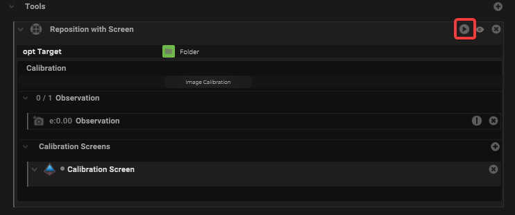
Once sufficient observations has been captured, return back to the camera object inspector, under the Tools tab, locate the Reposition tool and press the “play” icon in the header of the tool to apply the transformation to the target object.
Once the reposition has been applied, can check on the target object and see a translation in the coordinates should be applied.
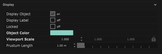
Display
| Name | Description |
|---|---|
| Display Object | If ticked, the object will be visible in the scene. If un-ticked, the object will not be visible. |
| Display Label | When on, there will be a label displayed next to the object. |
| Locked | When un-ticked, it activates keyboard shortcuts – pressing ‘E’ allows you to move and ‘R’ rotate. |
| Object Colour | Double click the colour block and this will open a colour picker. This can be used to change the object display colour. |
| Viewport Scale | Dimensions of the object in the viewport in meters. |
| Frustum Length | The frustum refers to the region that can be seen and rendered by a perspective camera. This parameter alters the length of the region in meters. |
Display Settings Tutorial
Filter
Mapping
Node Based
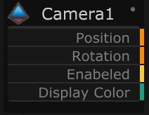
The object can be controlled and used as a node. The node is created by clicking and dragging the parameter on to the board.
| Name | Description |
|---|---|
| Type |
|
| Target Object | This is the object that will either be affected by the incoming values or output information. |
| Position | The directional XYZ values will be displayed here. |
| Rotation | The rotational XYZ values will be displayed here. |
| Enabled | When on, the parameter is active and enabled. |
| Display Colour | This colour block can be changed by changing the parameter. |
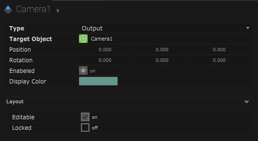
Layout
| Name | Description |
|---|---|
| Editable | When on, the node is editable. |
| Locked | When on, the node is locked into its position on the board. |