PIXERA is a 64-bit media server system for real-time media processing and compositing and management, which is built around the theme of usability.
Pixera Setup
| Name | Description |
|---|---|
| Update Handle Ids | When pressing the button the handle Ids will be updated. |
| Send Calibration Marker | When pressing the button a calibration mark will be sent. |
Pixera JSON/TCP Connection
| Name | Description |
|---|---|
| Server IP | This is where the IP address of the server can be added. |
| Interface | This is the IP address of the local network interface (NIC) which should be used for this connection. |
| Port | This is the port that the data package will be sent to. |
| Send Cyclic | When on repeating data packages will be sent. |
| Interval | The interval of the data packages can be input here. |
| ApiType | Direct API or TCP JSON can be selected. |

Pixera Actions
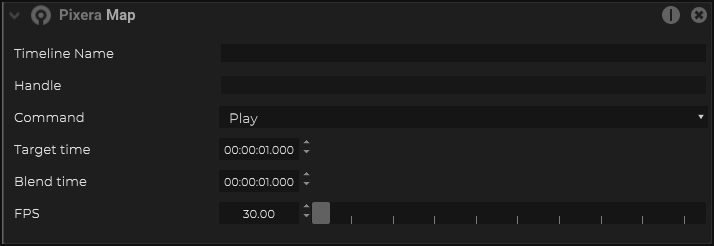
Within the Event system, Pixera Timeline Commands can be added as action.
| Name | Description |
|---|---|
| Timeline | Name of the timeline to control |
| Command |
|
| Target time | The target time to jump to |
| Blend time | the amount of time to blend the current position to the target position |
| FPS | FPS for the timeline to run at |
Pixera Mapping
SPNet Setup inside Pixera
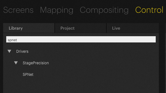
Inside Pixera Control, add the Stage Precision – SPNet driver
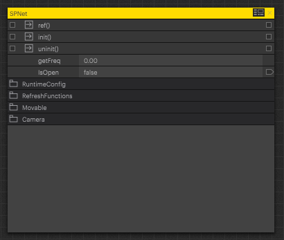
Create a control device within Pixera
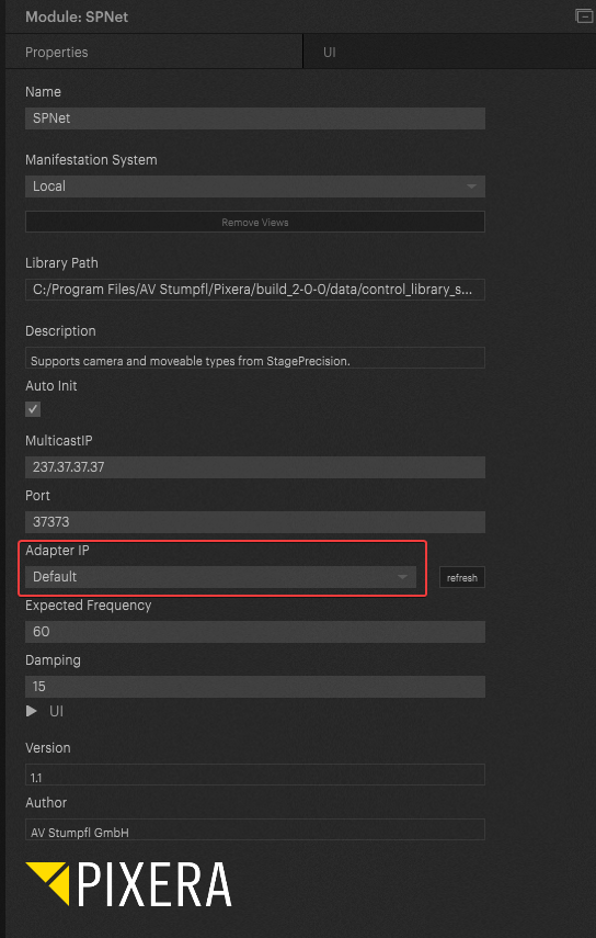
Select the SPNet control device and configure the Network Adapter that is being used to receive the SPNet data.
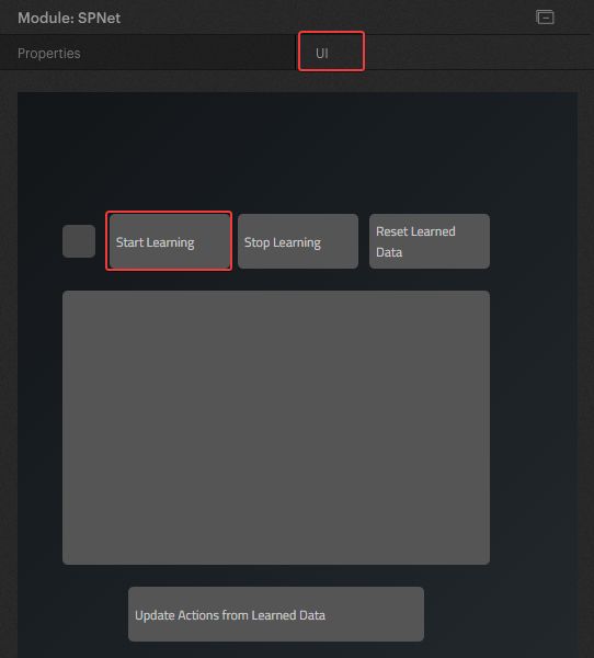
Select the SPNet control device and under the UI tab, click on the “Start Learning” button to get a list of all SPNet devices that are currently available
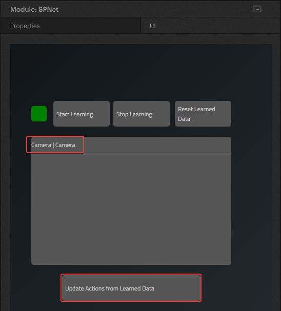
Once devices are detected and shows up in the list, click on the “Update Action from Learned Data”.
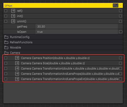
After that, within the SPNet control device, new controls are available and pins can be access for things like position, rotation, and lens data.
Maps Out
Send Position
| Name | Description |
|---|---|
| Type |
|
| Target | This is the target address for the information. |
| Get Handle | |
| Position Handle | |
| Frequency | The frequency of the positional data can be changed by manually changing the number, using the arrows or toggling the slider bar. |
| Damping | The amount of damping on the output values can be changed. The value can be changed manually changing the number, using the arrows or toggling the slide bar. |
| Send Position | When on, the position values will be output. |
| Send Rotation | When on, the rotational values will be output. |
| Send Trigger Mapping | This button outputs the trigger map. |
Transform
| Name | Description |
|---|---|
| Position |
|
| Rotation |
|
Advanced Sending Options
| Name | Description |
|---|---|
| Trigger Send | Pressing this button will send out a trigger value. |
| Use on Change | When on, the trigger will be output in a time interval. |
| Use on Interval | The time interval can be altered in milliseconds. |
| Timer Interval (ms) | The time interval can be altered in milliseconds. |

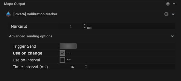
Calibration Marker
| Name | Description |
|---|---|
| Marker ID | The ID number of the calibration point can be added here. |
Advanced Sending Options
| Name | Description |
|---|---|
| Trigger Send | Pressing this button will send out a trigger value. |
| Use on Change | When on, the trigger will be output in a time interval. |
| Use on Interval | The time interval can be altered in milliseconds. |
| Timer Interval (ms) | The time interval can be altered in milliseconds. |
Compatible Output Objects
Node Mapping

| Name | Description |
|---|---|
| Module Info | The module information will be displayed here. |
| Target | This is the target address for the information. |
| Get Handle | This button triggers the node to find the handles. |
| Parameter Handle | The parameter handle name will be displayed here. |
| Type |
|
| Value | The output value will be displayed here. |


