
This is a virtual representation of a motorized winch, with a winch body, chain and hook. Objects attached to the hook and controlled by the movement of the winch.
The winch is able to receive and send out positional data.
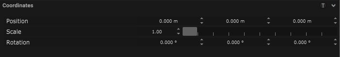
Coordinates
| Name | Description |
|---|---|
| Position | This will move the object along X, Y and Z axis in the local space. |
| Scale | Scale of the coordinate system. To scale the Object check the settings under “Display” |
| Rotation | Rotation of the object along X, Y and Z axis. |
Winch Control
| Name | Description |
|---|---|
| Control Type |
|
| Value | Movement of the winch from 0 to 100. |
| Value in % | True movement of the winch subobject inbetween the drive range minimum and maximum. |
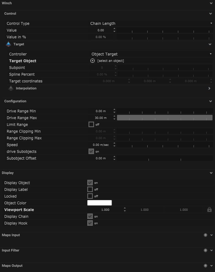
Winch Target
| Name | Description |
|---|---|
| Controller |
|
| Target Object | An object can be selected for the light to follow. |
| Subpoint | When the selected object is a combined or skeleton a single subpoint can be selected to track. |
| Spline Percent | When the selected object is a spline the area of the spline can be selected by percentage. |
| Target Coordinates | The target coordinates can be selected. |
Interpolation
| Name | Description |
|---|---|
| Mode |
|
| Damping | This is the amount of dampening done to the incoming data, the smaller the number the more the effect. |
| Window Size | This indicated the size of the selection window of the data, the larger the number the larger the amount of data will be used by the moving average and weighted moving average mode types. |
Configuration
| Name | Description |
|---|---|
| Drive Range Min | The closest distance the chain or object can be to the winch. |
| Drive Range Max | The maximum distance that the chain can travel from the winch. |
| Limit Range | If ticked it enables the use of the range clipping min and range clipping max. |
| Range Clipping Min | Minimum distance the winch can travel within the drive range min. |
| Range Clipping Max | Maximum distance the winch can travel within the drive range max. |
| Speed | Maximum speed which the winch subobject can travel. |
| Drive SubObjects | If ticked this will control any objects which have been made a child of the winch, as if they are attached to the winch chain. |
| SubObject Offset | Offset distance between the subobject and winch body. |
Display
| Name | Description |
|---|---|
| Display Object | If ticked, the object will be visible in the scene. If un-ticked, the object will not be visible. |
| Display Label | When on, there will be a label displayed next to the object. |
| Locked | When un-ticked, it activates keyboard shortcuts – pressing ‘E’ allows you to move and ‘R’ rotate. |
| Object Colour | Double click the colour block and this will open a colour picker. This can be used to change the object display colour. |
| Viewport Scale | Dimensions of the object in the viewport in meters. |
| Display Chain | A virtual representation of the chain is visible when ticked and turned on. |
| Display Hook | A virtual representation of the hook is visible when ticked and turned on. |
Display Settings Tutorial
Mapping
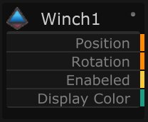
Node Based
The object can be controlled and used as a node. The node is created by clicking and dragging the parameter on to the board.
| Name | Description |
|---|---|
| Type |
|
| Target Object | This is the object that will either be affected by the incoming values or output information. |
| Position | The directional XYZ values will be displayed here. |
| Rotation | The rotational XYZ values will be displayed here. |
| Enabled | When on, the parameter is active and enabled. |
| Display Colour | This colour block can be changed by changing the parameter. |
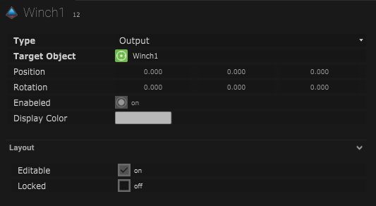
Layout
| Name | Description |
|---|---|
| Editable | When on, the node is editable. |
| Locked | When on, the node is locked into its position on the board. |