SPNet is a Stage Precision own protocol which can be used to communicate with other SP documents.
SPNet Setup
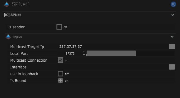
Is sender – When off the Stage Precision document will receive SPNet. When on the Stage Precision document will output SPNet.
Input
| Name | Description |
|---|---|
| Multicast Target IP | This is where the IP address of the multicast can be entered. |
| Local Port | This is the port that will receive data from other devices. |
| Multicast Connection | When on, data can be sent to multiple recipients. |
| Interface | This is the IP address of the local network interface which should be used for this connection. |
| Use in loopback | When on the data will be looped back on the IP network. |
| Is Bound | This will be on when the IO connection is bound to a network. |
Output
| Name | Description |
|---|---|
| Multicast Target IP | This is where the IP address of the multicast can be entered. |
| Local Port | This is the port that will receive data from other devices. |
| Multicast Connection | When on, data can be sent to multiple recipients. |
| Use in loopback | When on the data will be looped back on the IP network. |
| Refresh Time (ms) | The refresh time of the output can be set here in milliseconds. |
| Interface | This is the IP address of the local network interface which should be used for this connection. |
SPNet Mapping
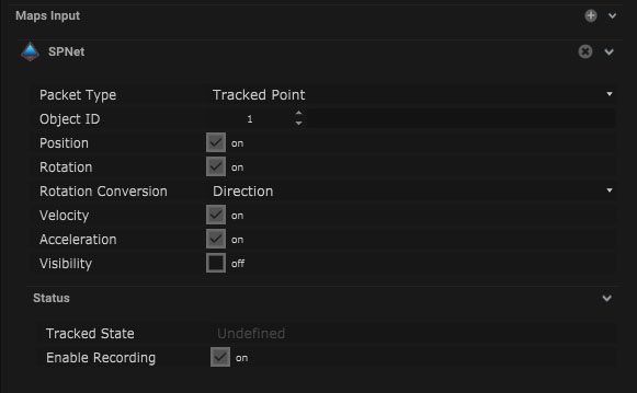
Maps In
| Name | Description |
|---|---|
| Packet Type |
|
| Object ID | The specific object number or ID can be selected here. |
| Position | When on the positional data will be used. |
| Rotation | When on the rotational data will be used. |
| Rotation Conversion |
|
| Velocity | When on the velocity data will be used. |
| Acceleration | When on the acceleration data will be used. |
| Visibility | When on the input visibility data will be used. |
Compatible input objects
- Tracker
- Skeleton
- Camera
- Rigid Body
- Centroid
- Volume
- Moveable
- Winch
- Winch 3
- Light Fixture
- Laser Fixture
- Pixel
- Multipixel
- PTZ Camera
- Spotlight
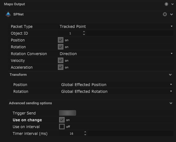
Maps Out
| Name | Description |
|---|---|
| Packet Type |
|
| Object ID | The specific object number or ID can be selected here. |
| Position | When on the positional data will be output. |
| Rotation | When on the rotational data will be output. |
| Rotation Conversion |
|
| Velocity | When on the velocity data will be output. |
| Acceleration | When on the acceleration data will be output. |
| Visibility | When on the input visibility data will be output. |
Transform
| Name | Description |
|---|---|
| Position |
|
| Rotation |
|
Advanced sharing options
| Name | Description |
|---|---|
| Trigger Send | Pressing this button will send out a trigger value. |
| Use on change | When on, the trigger will be output when the values change. |
| Use on Interval | When on, the trigger will be output in a time interval. |
| Timer Interval (ms) | The time interval can be altered in milliseconds. |
Compatible output objects
- Skeleton
- Camera
- Rigid Body
- Centroid
- Volume
- Moveable
- Winch
- Winch 3
- Light Fixture
- Laser Fixture
- Pixel
- Multipixel
- PTZ Camera
- Spotlight
- Area
Node Based Mapping
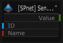
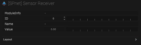
Sensor Receiver
| Name | Description |
|---|---|
| Module Info | The module name will be displayed here when connected. |
| ID | The sensor ID will be displayed here when connected. |
| Name | The of the sensor can be manually input. |
| Value | The receiver value will be displayed here. |
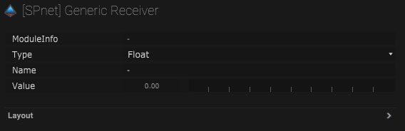
Generic Receiver
| Name | Description |
|---|---|
| Module Info | Module information will be displayed here when connected. |
| Type |
|
| Name | The output name can be added manually. |
| Value | The output value will be displayed here. |
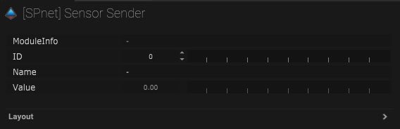
Sensor Sender
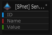
| Name | Description |
|---|---|
| Module Info | The module information will be displayed here. |
| ID | The ID number of the sensor can be added here. |
| Name | The name of the sensor can be added here. |
| Value | This is the output value. |
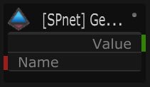
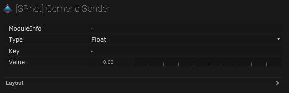
Generic Sender
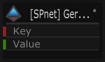
| Name | Description |
|---|---|
| Module Info | The module information will be displayed here |
| Type |
|
| Key | Output key can be added here. |
| Value | This is the value that will be output. |
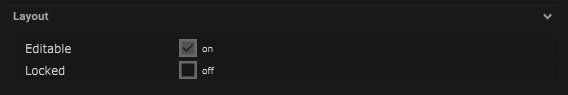
Receiver/Sender Layout
| Name | Description |
|---|---|
| Editable | When on, the node is editable. |
| Locked | When on, the node is locked into its position on the board. |