
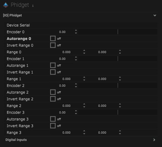
Phidget Setup
| Name | Description |
|---|---|
| Device Serial | The serial number of the device will be displayed when connected. |
| Encoder 0 | The value of encoder 0 will be displayed here. |
| Autorange 0 | When on, the ranges will be generated automatically. |
| Invert Range 0 | When on, the min and max range values will be inverted. |
| Range 0 | The minimum and maximum values can be added here. |
| Encoder 1 | The value of encoder 1 will be displayed here. |
| Autorange 1 | When on, the ranges will be generated automatically. |
| Invert Range 1 | When on, the min and max range values will be inverted. |
| Range 1 | The minimum and maximum values can be added here. |
| Encoder 2 | The value of encoder 2 will be displayed here. |
| Autorange 2 | When on, the ranges will be generated automatically. |
| Invert Range 2 | When on, the min and max range values will be inverted. |
| Range 2 | The minimum and maximum values can be added here. |
| Encoder 3 | The value of encoder 3 will be displayed here. |
| Autorange 3 | When on, the ranges will be generated automatically. |
| Invert Range 3 | When on, the min and max range values will be inverted. |
| Range 3 | The minimum and maximum values can be added here. |
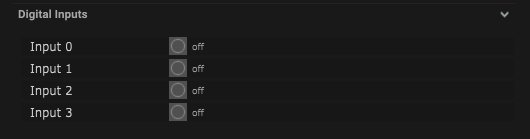
Digital Inputs
| Name | Description |
|---|---|
| Input 0 | When on, this input is connected. |
| Input 1 | When on, this input is connected. |
| Input 2 | When on, this input is connected. |
| Input 3 | When on, this input is connected. |
Compatible Input Objects
*  Click this icon to range the incoming Values.
Node Mapping

| Name | Description |
|---|---|
| Module Info | The module information will be displayed here when connected. |
| Input 0 | This will be on when the output is connected. |
| Input 1 | This will be on when the output is connected. |
| Input 2 | This will be on when the output is connected. |
| Input 3 | This will be on when the output is connected. |

Layout
| Name | Description |
|---|---|
| Editable | When on, the node is editable. |
| Locked | When on, the node is locked into its position on the board. |